For many of us, living in an HOA-managed neighborhood is a given. There are typically HOA restrictions on antennas – typically No Antennas in the newer neighborhoods. Now I’m not going to debate the pros/cons or rights/wrongs about HOA. The main purpose of HOA’s is to protect everyone’s home values, which is beneficial to us all. However, we ham radio operators need options to operate and yet somehow “fit in” and avoid being a problem. This is why I designed the Purple Martin Birdhouse Stealth Antenna.
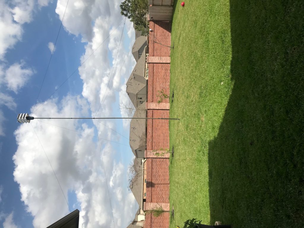
Birdhouses are typically not restricted by HOA covenants. My birdhouse antenna has been “hidden in plain sight” and in operation for several years with no issues, no complaints, and excellent operating results. My original hypothesis was that a birdhouse could be used to get the antenna elements high off the ground to around 32″ or so, and far enough away from the house that RF with power levels up to 1,000 watts would not cause RFI issues for me or my neighbors.
Key “open stealth” design is making the antenna elements appear similar to the guy lines. In fact, the antenna elements ARE guy lines and serve dual purposes – support the antenna in the wind and provide resonant operation on the desired ham radio HF bands.
The Design
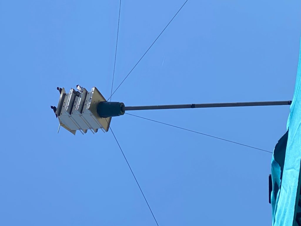
I wanted the birdhouse antenna to be functional, not only as a decent performing HF antenna system but also as, well, a purple martin birdhouse! Seeing birds using the birdhouse during purple martin season goes a long way toward selling the birdhouse as beneficial, legitimate, and acceptable.
I probably went a bit overboard on the birdhouse. I invested about $300 in a modern, aluminum purple martin birdhouse I bought from a local bird store. This particular model has 6 total bird rooms. I’m going to focus more on the key elements of the antenna design and not on the birdhouse itself for this post. Keep in mind that as with any antenna being supported atop of a mast or tower, one must take into consideration the surface area of the birdhouse and how much force will be created by wind pressure during storms. The guy lines and mast must support these forces without failing or it will all come crashing down at some point.
There were numerous challenges that had to be addressed for this antenna to work. First, a suitable, affordable mast of some kind was needed. I chose some inexpensive military surplus fiberglass poles available on ebay. These 4-foot poles fit nicely together and provide a sturdy base upon which to mount the birdhouse, as shown above. I used 8 of them to get up 32″, which in my experience is the minimum height for decent inverted vee performance with multi-band dipole antennas on 20 meters (less than ideal on 30 and 40 meters but livable vs. no antenna at all).
A key challenge was how to hide the balun and other “guts” of the antenna system while making it all look natural and aesthetically pleasing at the same time. My solution ended up being practical, cheap, and inexpensive.
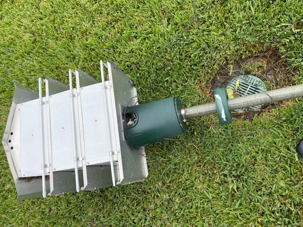
As shown above, the antenna components are covered up by a green plastic cover. This is actually an upside-down irrigation valve housing you can pick up at your local hardware store for $10. I also found a small green plastic bottom cover to cover up the hose clamp seen above (I used a small tie-wrap to secure the bottom cover plate).
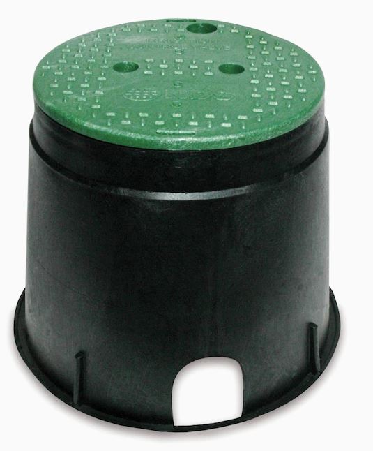
I drilled out the removable cover (green above) using a doorknob hole bit held by my vise. I then spray-painted the whole thing a dull green color so that it would look uniform. Then I drilled some holes in the sides to provide a pathway for the two (2) antenna elements and two (2) guy lines to pass through.
Hose clamps were used to secure and snug the upside-down irrigation valve housing to the bottom of the birdhouse and the fiberglass mast.
The coax cable runs up from underground into the bottom mast section, and up to a hole that was drilled out to allow the coax and connector to pass through the topmost mast section, within the mast area covered by the irrigation valve housing.
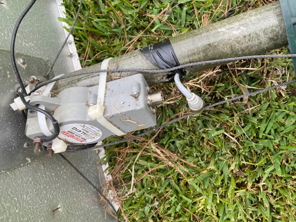
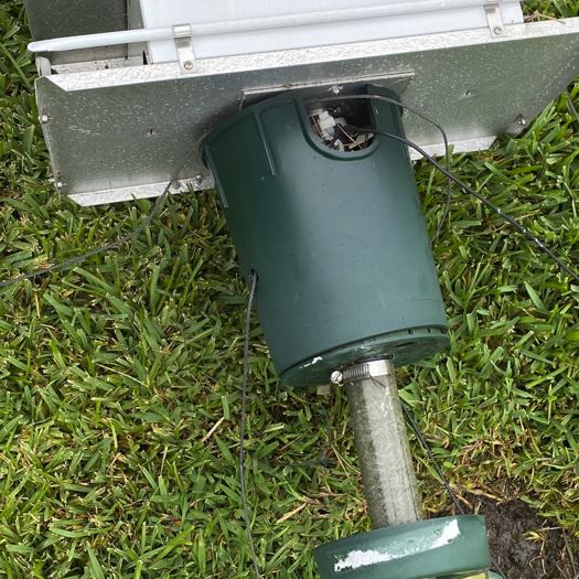
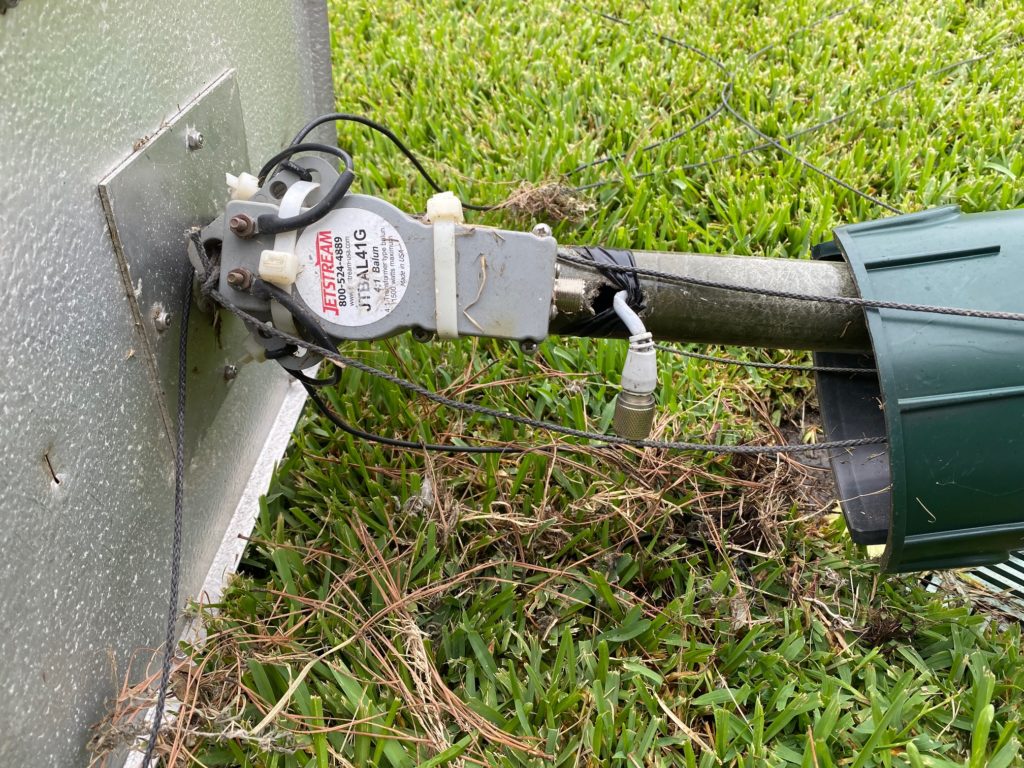
There’s a legal limit 4:1 balun (also from ebay) that’s used for impedance matching the multiband dipole elements to the 50-ohm coax at the feed point. I will not delve into the underlying dipole design in any detail, as there are plenty of off-the-shelf and well-designed multi-band wire dipoles to choose from today.
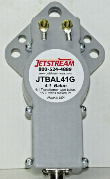
This balun keeps the common mode currents isolated, for the most part, from the coaxial feedline, minimizing RF feedback issues inside the shack. It also serves as a very sturdy mount point to connect the mast with the supporting antenna wire elements.
I also used a choke on the 100′ RG8X coax before it enters the window to my house. This further minimizes CMC from entering the shack.
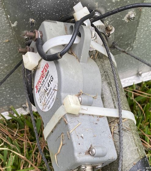
The above closeup shows the top of the fiberglass mast mounted to the bottom of the birdhouse using a stainless steel bolt with an aircraft nut. There’s also a hose clamp around that area, which acts as a backstop for the guy lines. The antenna elements are looped through the strong plastic balun, which is strapped to the mast using very strong white tie wraps. This is all the ugliness of the antenna that is hidden from plain sight using the upside-down irrigation value cover.
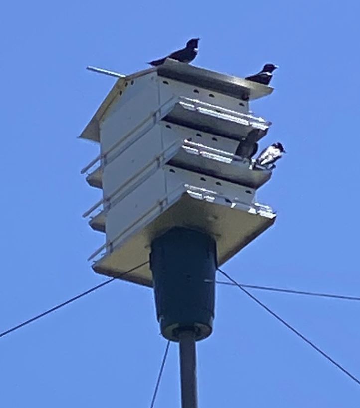
Above we see the guy lines poking through the antenna element cover. The topmost guy lines are the two non-element support lines. The bottommost lines are the antenna elements. All are black in appearance and look very similar to the naked eye. In fact, the birds and birdhouse end catching the eye for the most part, with the guy lines looking normal and necessary to keep the birdhouse stable atop the mast.
Finally, to raise the birdhouse, antenna, and mast system, I mounted the guy lines (4 each from the top near birdhouse plus another 4 guy lines mounted to the mid-point of the mast about 16 feet up. Each guy line was secured to eye bolts on the wooden fence 4×4 posts on each yard side, the brick-looking fence that runs along the back, and a brick column on my back porch. I kept the guy lines up high enough to avoid interfering with normal traffic from yard mowing, visitors, etc.
Starting with the four side guys, I leaned the birdhouse and mast upright, then tightened the side guys, keeping the fiberglass mast from bending too much that it might break (some flexing is okay). Step by step, the birdhouse is raised until fully upright, then all 8 guy lines are adjusted to be taught and supportive in its final position. The bottom of the mast is buried just a few inches below the grass surface, along with the coax entering inside the bottom of the fiberglass mast.

The result. A stealthy purple martin birdhouse antenna that covers 10 meters through 40 meters (some bands require a tuner, as with any multi-band dipole).
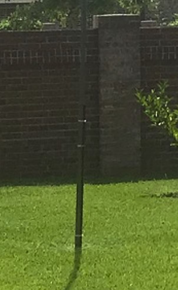
The bottom of the mast is secured to a 5′ T-post driven into the ground. I used two large white plastic tie wraps, plus another stainless hose clamp, to secure the bottom mast section and keep it on the ground.
Although not easy to see in these pictures, I also used black electrical tape to bind each fiberglass mast section to the next at each joint. This was an extra precaution, in case severe updrafts caught the underside of the birdhouse, attempting to lift it a few inches. The electrical tape prevents each section from moving or being separated from the next. In theory, properly tightened guy lines should make the tape unnecessary, but I wanted the extra safety measure as I knew the wind loads could be substantial during tropical storms, hurricanes along the Gulf Coast and severe thunderstorms with microbursts we get here in Texas.
Guy Line Note: for guy lines, I have been using polyester-coated Kevlar lines with 770 pounds breaking strength. These lines have proven durable, strong, and do not stretch much at all, a must for ensuring mast-mounted antennas remain stable under high and bursty wind conditions.
Tuning the Antenna
As with any inverted-vee antenna created from a dipole, the length of the antenna elements must be tuned and tweaked for proper resonance on the desired operating bands. In my experience, off-the-shelf dipole antennas configured into inverted-vee configurations must be adjusted in length.
In my case, I chose to optimize the resonance around the 20-meter band. To do this, I first tied the ends of the two antenna wire elements to actual guy lines using proper knots. Then, I soldered some short lengths of #26 black polystealth antenna wire to the end of each to adjust for resonance.
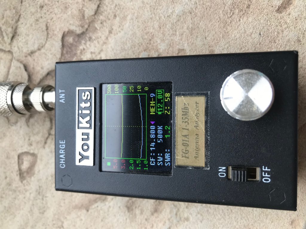
As shown above, I use a YouKits FG01A antenna analyzer, which provides a tuning signal and graph of the SWR as seen at the coax for the antenna. I then shorten the antenna endpoint pigtails little by little until the desired SWR low point in the 20-meter band is reached. Finally, SWR is sanity-checked on the remaining bands supported by the multi-band antenna design (a topic I won’t cover in-depth in this post).
Periodic retuning. Over time, I noticed some drift from ideal SWR after about a year of usage. I attribute this drift to the inevitable stretching of the copper wire used as guy lines. These wires are load-bearing, and get significant pressure on them over time, stretching the lengthening the copper wires some. All wire antennas are subject to some initial stretch (unless you pre-stretch them, which I did not do). It’s easy enough to address – just trim a few inches from the tuning pigtails at the end of each antenna element. I only had to do this once.
Testing the Antenna
After initial tuning, the moment of truth finally arrived – connecting the coax to the radio and amplifier to take it for a spin. I began by using WSPR across all of my various target bands and ran multi-band tests overnight. To my surprise with just a few watts, my birdhouse antenna was heard around the world and was hearing great as well.
I have enjoyed years of stealthy amateur radio operation using the birdhouse antenna. The birds like it too! Each year the purple martins start showing up around February/March and stay until around August, nesting, eating mosquitoes and keeping the local biting insect population at bay, and enabling me to work the world of HF from my HOA controlled site.
Flagpole vertical antennas are another alternative, but one I decided to avoid because of the need for a tuner at the feed point, many radials required for decent performance, and the fact I did not want a flag pole in my back yard. I believe the additional gain from my inverted-vee antenna is well worth all of the effort in designing, testing, and refining this design.
In summary, where there’s a will, there’s usually a way. When I set out on this journey, there were many unknowns and questions… would the neighbors accept the birdhouse? would the HOA get upset by it or push back? Would the antenna perform well enough to be worthwhile? would birds actually use the birdhouse?
As it turned out for me, the birdhouse antenna worked out exactly as intended, providing me with decent performance, a working purple martin birdhouse, and years of productive DX and local ham radio operation.

Very nicely engineered! “Hidden In Plain Sight”
Thanks for sharing.
John-W5PDW
That is a nice bird house
After looking at a few of the articles on your web page, I really like your
way of writing a blog. I saved as a favorite it to my bookmark site
list and will be checking back soon. Please check out
my web site too and tell me what you think.
my site خرید بک لینک دائمی
Good post but I was wondering if you could write a litte more on this topic?
I’d be very grateful if you could elaborate a little
bit further. Cheers!
Hello! This is my first visit to your blog! We are a group of volunteers and starting
a new initiative in a community in the same niche.
Your blog provided us valuable information to work on.
You have done a extraordinary job!
my webpage – เว็บวาไรตี้
Withh a fantastic neew customer incentive, there’s nnot a lot incorrect with Caesars Sportsbook.
My blog post webpage
What’s up, yeah this article is actually pleasant and I
have learned lot of things from it concerning blogging.
thanks.
I read this post fully concerning the comparison of hottest and preceding technologies, it’s remarkable article.
Ahead of you commence applying for loans for undesirable credit,
we propose looking at you credit report.
Look at my blog … 무직자 대출
For latest information you have to pay a visit web and on web I found this website as a best web site for most recent updates.
Wow, that’s what I was looking for, what a stuff! existing here at this blog, thanks admin of this web site.
Good write-up. I absolutely appreciate this website. Keep writing!
Here is my site :: http://www.greaterlondonescorts.com
Hi there, I desire to subscribe for this webpage to obtain latest updates, thus where can i do it please help.
I must thank you for the efforts you’ve put in writing this blog.
I’m hoping to check out the same high-grade
content from you in the future as well. In fact, your creative writing abilities has encouraged me to get
my own website now 😉