After many years of part-time experimentation, prototyping and numerous failed attempts, I am pleased to say that I finally broke through and found a combination of technologies that make it all worthwhile. As a result, below please find the “ResonantOne” (working name) switched multiband antenna. There is also a prototype of a corresponding dipole antenna, which will be covered in a later post.
The original goals were to create a no-compromise, naturally-resonant, multi-band antenna with no moving parts (i.e., no stepper motors or physically moving elements), no traps, no coils, and with near-instant automatic tuning, and 10-years or more operation with no maintenance. Oh yeah, and low to moderate cost was another objective so that the majority of ham radio operators could afford it without breaking the bank.
Many initial attempts failed, largely due to current drain requirements and the need to wake up the antenna switch (relay) controllers remotely. Earlier this year, I made the final breakthrough that enables it all to work together at low power – the missing piece turned out to be Plastic Optical Fiber (POF) technology. As a result of these discoveries and breakthroughs, in July 2019 a patent was filed, making the design disclosed here “Patent-pending”, as well as copyrighted.
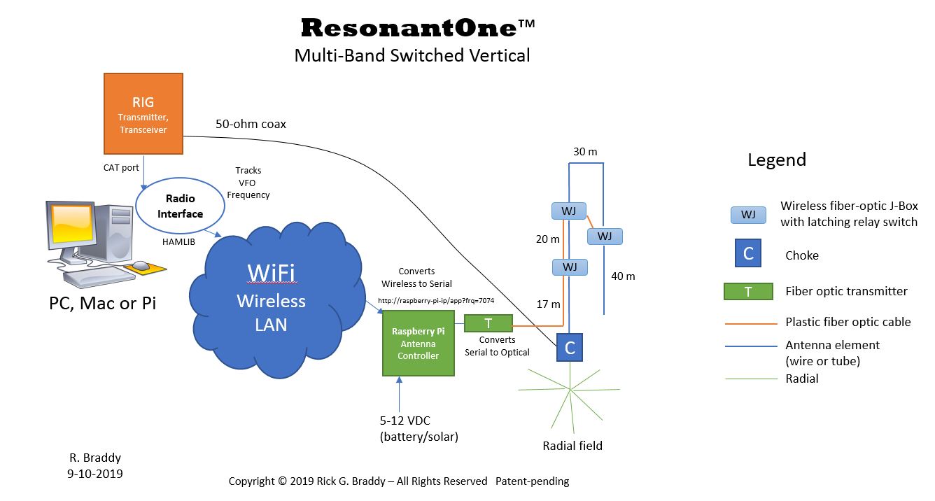
As shown above, this vertical antenna requires radials (like most verticals). Starting at the upper left of the diagram, the radio rig VFO frequency is read via a CAT port by a Radio Interface program, which uses HAMLIB to integrate with a wide range of radio devices. From there, the Rig’s frequency is transmitted to a Raspberry Pi, connected via WiFi (or hardwired Ethernet alternatively). The Raspberry Pi is the antenna controller, located nearby the vertical antenna base. It receives the Rig frequency updates and then transmits those via serial port to the “T” transmitter interface module, a daughterboard that plugs into the Pi. This board contains a plastic fiber optic LED, which converts the electrical serial data stream into a series of light pulses. The light signal is fed via plastic fiber optic cable into the antenna system.
The light signal travels across the orange line to the first switch box, called a WJ or wireless junction box. Each WJ box houses an RF latching relay, which is used to switch antenna elements in and out for each band to achieve resonance.
In the above diagram, we see a switched vertical configured for four bands, which requires 3 WJ boxes. The WJ boxes are daisy-chained together, whereby each WJ-box repeats the incoming signal for the next device down the line. Although configurable, the initial units operate and 19.2 Kb, which is plenty fast enough to perform antenna switching in a few milliseconds.
You may be wondering, what’s inside each of those WJ-Boxes to make it all work? The following overview describes the basic operation of the antenna switch box.
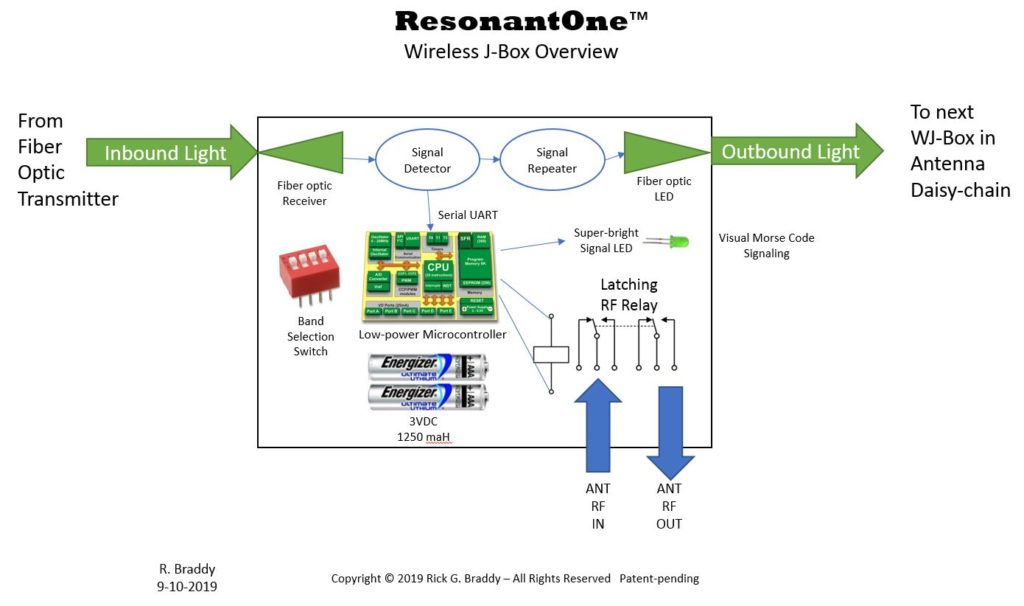
Each WJ-box receives an incoming light signal that’s received by a fiber-optic receiver device, which converts the light signal into a small current. That current is then amplified and detected, recreating the original square wave serial data signal; ie., a 19.2Kb serial data stream. That signal flows first into the Signal Repeater, where it modulates a fiber optic LED, converting the electrical signal back into an outbound light signal, that’s passed down the line to the next WJ-box along the antenna segment, as shown in orange in the first diagram above.
The serial data stream is also passed into a Microchip microcontroller, which manages and controls the switch box operation. It reads a Band Selection Switch to determine which ham band the WJ-Box is assigned; e.g., 20 meters. This tells the microcontroller when it should open vs. close the relay, based upon the received rig VFO frequency. It can provide signaling of error codes and diagnostic information via a super bright green LED, which blinks using visual Morse code. For example, when it opens the relay, it blinks “O”, and “C” when the relay is closed. If errors arise, it blinks “E” followed by an error code number.
The entire device consumes around 1 microamp (yes, just one-millionth of an amp) when sitting idle. The device only awakens for a few milliseconds whenever there’s an inbound light signal received, processes that command, then goes back into low power sleep. So it’s only awake for up to 15 milliseconds and most of that is spent waiting for the latching relay to open or close and/or flashing visual morse if diagnostic signaling is enabled.
So there you have it. The first working fiber-optic switched antenna system. Many thanks to all of my fellow ham radio friends who consulted, kibitzed, advised and assisted me over the past several years. This would not have been possible without your encouragement and support.
So what’s next? Well, that’s an excellent question. I’m going to build out a few more prototype antennas for some local hams in my club, to do some independent testing, then figure out how best to make this technology available more broadly. I’m not doing this for the money, but because of the patents involved, I am reserving commercial rights to help recover legal and other costs and to someday license the rights to others, should there be that level of interest.
The design will likely be licensed initially for personal use and perhaps some form of open source development collaboration and boards may be available in kit form. Who knows, perhaps someday someone will want to commercially produce the antennas – we shall see. I’m in no hurry – still having fun pushing the state of the art forward and experimenting with new antenna concepts. Once I determine how best to proceed, more details will be posted.

Recent Comments