As discussed in the ResonantOne Multiband Switched Vertical Antenna blog post, this post covers the corresponding dipole antenna, which is shown below.
(CLICK IMAGE TO ENLARGE)
Interestingly, during last night’s NARS (Northwest Amateur Radio Society) ham radio club meeting, we were fortunate enough to have Bob Naumann W5OV with DX Engineering share a nice antennas 101 overview presentation with us. One of the things Bob said that caught my attention was that many ham radio operators want to put up a single antenna and then expect it to perform well over several HF bands. For example, the G5RV is commonly deployed by new hams, followed by lackluster results and disappointment, leading some to abandon the hobby.
Instead, Bob said one would be better off putting up multiple monobanders, such as a separate dipole for 80 meters, another for 40 meters, and another for 20 meters. In fact, I know many hams who do exactly that and have 3 or 4 inverted vees or dipoles strung up from their tower(s) and trees. Of course, this takes extra effort to deal with all these separate antennas, their feedlines and switching, potential interactions not to mention the complaints about so many antennas from the XYL and/or neighbors.
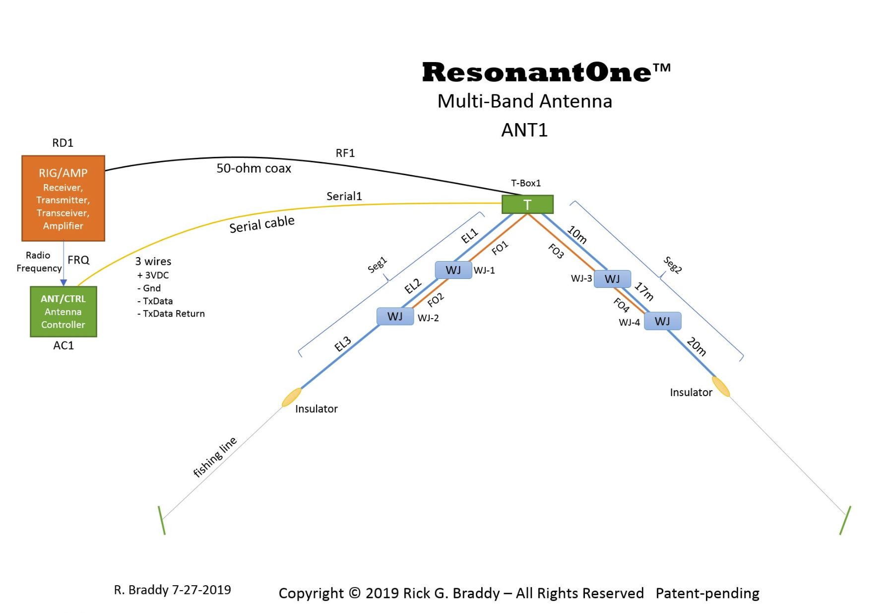
The Multiband Switched Dipole was designed to address these limitations by making a no-compromise, multi-band antenna system that’s natively resonant and auto-tuning. Referring to the above diagram, here’s how it works.
We see here an inverted vee configuration, with several boxes labeled “WJ”, which stands for wireless junction box. Each WJ box contains a latching relay along with a PIC microcontroller that makes switching decisions that tunes the antenna system to resonance for the band that the Rig is currently operating on; i.e., the band the rig’s transmitter VFO is set to. For example, we see on the right side of the inverted vee the antenna segment labeled Seg2, which contains two WJ boxes, WJ-3 and WJ-4. The blue lines represent the antenna elements comprising the 10, 17 and 20-meter elements. These bands were somewhat arbitrarily chosen, as any amateur band from 160m through 2m can readily be supported.
As the rig’s VFO is tuned from one band or frequency to another, the Antenna Controller labeled AC1 in green receives the latest VFO frequency update. It then sends significant frequency changes across a serial cable (or wireless signal) to a T-Box, labeled “T”, which converts the electrical serial signal (e.g. 19.2 Kb serial data signal like you see from a USB or CAT port) into a corresponding light signal, which is fed through a plastic fiber optic cable to the first WJ-Boxes, in this case WJ-1 and WJ-3. The WJ-Boxes are daisy-chained in series along each antenna segment, repeating their signals down the line, as depicted by the orange lines in the diagram.
The RF signal feeds the inverted vee just like any other monoband equivalent. Instead of using traps, coils or other components, an RF relay within each intelligent WJ box opens and closes the appropriate antenna elements for resonance. This results in the similar performance of the switched multi-band antenna that one would expect from multiple separate monoband antennas.
The plastic fiber optic cable, which is non-conductive, turned out to be the critical design element to make this possible. Because the fiber optic signal carries low power energy in the form of light, it actually transfers that energy from the transmitter T box across the fiber optic cables into each WJ box, where it gets converted into an electrical current again. This electrical current then gets amplified and wakes up the microcontroller, which receives the 19.2 Kb serial data signal containing the VFO frequency, as described in the earlier blog post.
This wakeup signal energy being remotely transferred turns out to be significant. The biggest challenge with the WJ Box is keeping battery power drain to a minimum, particularly when idle (and antennas spend most of their time not switching bands). Minimizing the idle quiesce current consumed by each WJ box was the biggest design hurdle. The use of low power light energy to wake up the sleeping MCU turned out to be the secret to making this design plausible for real-world applications.
Today’s MCU’s are designed to support ultra-low-power sleep modes in the nano amp range. The issue is waking them up via an interrupt whenever there’s actually something to do, like make a switching decision. The microwatt level light signal transferred over the plastic fiber optic cable solves that problem.
The other challenge was minimizing the relay contact capacitance. The original relay selection exhibited about 2 pF of capacitance across the open relay contacts. This is enough to shift the 20 meters (relay open) resonance point by up to 600 Hz, from 14.2 MHz to 13.6 MHz! The main disadvantage is that this capacitance reduced the usable bandwidth by about 33%.
Moving to a different relay with wider contact spacing (and higher voltage rating) reduced this capacitance down to 0.2 pF, which has a negligible impact on the antenna’s operation. Because the relays sit at the high voltage endpoint of each antenna element, choosing the right relay is another critical design choice. Of course, because a latching relay is needed to avoid ongoing current drain, the number of relay options is limited.
It’s great to finally have an operating prototype, after years of failed attempts trying various approaches that resulted in different dead-ends. As with everything in life, there are tradeoffs. Instead of multiple monobanders with antenna feedline switching, this antenna requires inline switching and fiber optic cables and a VFO tracking path. What’s the old saying, “there’s no free lunch”?
So far during prototype testing, the plastic fiber optic cables exhibited up to 3 dB loss per 10 meters of cable. Based upon the light signal levels and the corresponding received voltages being observed at each WJ-Box, I’d estimate that at least 30 meters of cable can be used without any loss of reliability. This means 160 meters or even longer segments should be supportable.
So achieving natively resonant, high-efficiency multi-band antennas requires some tradeoffs. We are certainly accustomed to that, and this antenna design is no different – it’s just a matter of which set of tradeoffs one wants to make I suppose. Hopefully, this design moves the multiband antenna ball forward in some useful ways that will be of benefit. Time will tell.

Recent Comments